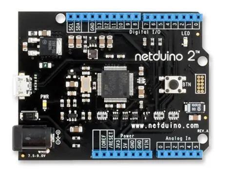
Do you own one of these? I suspect that some of you may be like me and still have one in a closet or box collecting dust. Please, don’t throw them away. They are still useful boards and if you’re willing to take a few minutes to setup a few tools you’ll see for yourself. Don’t let the name fool you, these devices are not exclusive to the .Net framework. The board contains a powerful 32-bit ARM MCU (micro controller unit) with a 25Mhz clock crystal pushing the internal speed of some components to 120Mhz. The MCU is a variant of the STM32F205 which has a lot of capabilities. The number of peripherals this chip supports is quite impressive. The Netduino 2 board boasts 22 GPIO pins, 6 PWM Channels, 4 UART ports, I2C, SPI and more.
In a previous post I wrote about my journey of reviving a couple of Netduino 2 boards that had gotten lost in the back of my electronics box. That article included a basic set of instructions for programming it with both the Arduino IDE and the STM32Cube tools. My second article took a closer look using the Arduino IDE for programming a Netduino programming. I’d definitely recommend that setup for programming these boards. The amount of examples and assistance available for Arduino makes using it a breeze and this board is compatible with a lot of the shields available for Arduino.
This post will focus on the more advanced STM32Cube toolset. Here we’ll learn how to setup and configure the board and write some C code to show off the boards basic features. We’ll still keep it pretty simple so even if you haven’t used STM32Cube before, it should be easy to follow along.
Software Setup
To start, you’ll need to make sure you have a few tools installed on your PC. If you’ve followed along with the other articles you may have a few of these already installed. Since I use VS Code for a lot of other projects, I chose to use the STM32Cube for VS Code extension. STMicroelectronics has a short video walking through the install and configuration.
Prerequisites
- STM32CubeCLT
- STM32CubeMX
- STM32CubeProgrammer (I installed this but it may be optional)
- STM32Cube for Visual Studio Code
Configuration
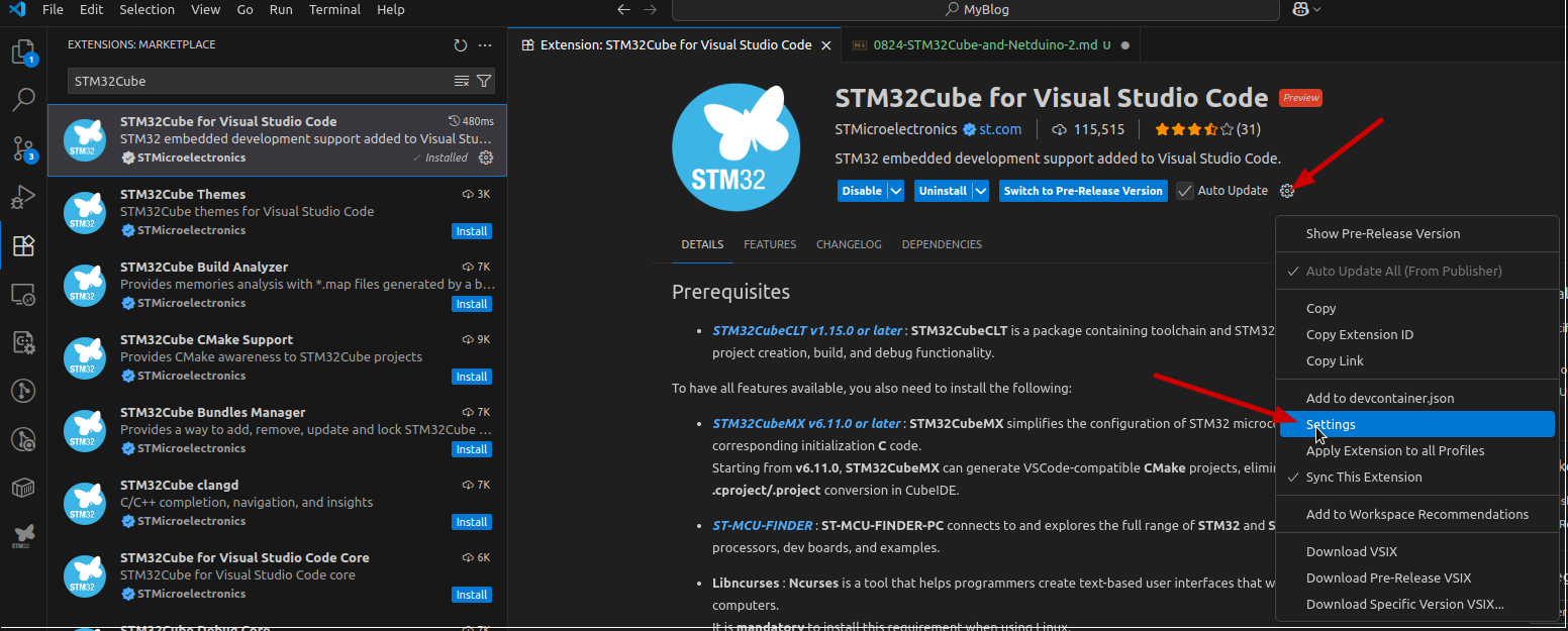
Once you’ve installed the tools above you’ll need to tell the VS Code extension where to find the CubeMX and CLT. Go back to the VS Code extension page and use the gear icon (below the description and just to the right of the blue buttons) to get to the settings window.
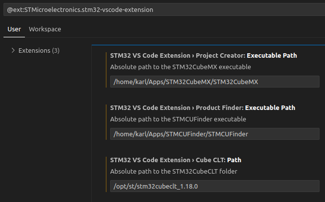
Here’s a snapshot of my settings page (Linux).
Creating Your First Project
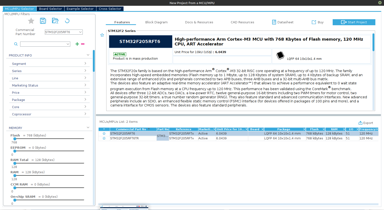
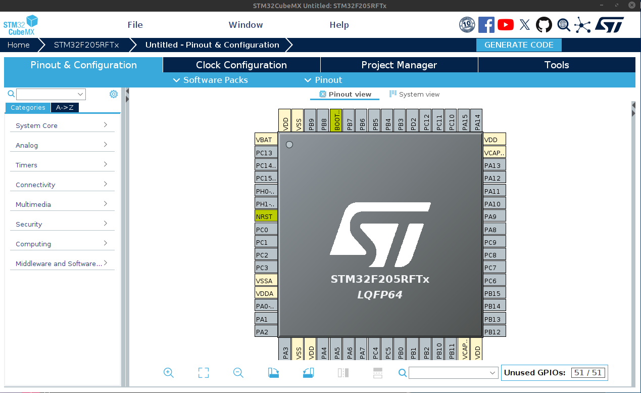
It’s time to get that LED blinking. Bring up the VS Code window if it’s not already up. You should have a new icon in the activity bar on the left that should reveal the STM32Cube tools window. Let’s start with the Launch STM32CubeMX link. As the external tool opens, you may notice it download some support packages. If you get any errors during this step, create an account on the STM32 site. I found that once I created my account and logged into their site I no longer saw that error. Once the tool opens, select the ‘Start My Project from MCU’ (MCU = Microcontroller Unit) link in the middle of the screen. This will open the product selector window. Make sure the “MCU/MPU Selector” tab is selected and enter STM32F205RFT6 in the Commercial Part Number box. Now highlight that same part number in the list on the bottom right. Once selected, the top right section will display details about the MCU, including links to ST product pages and datasheet. Useful if you want to dive deeper into this product line. You’re screen should look something like this.
Now press the Start Project button at the top right which will setup the initial project details and download any MCU specific files necessary for code generation. Once complete it will take you back to the STM32CubeMX window with the Pinout & Configuration page opened.
Schematics and Pin Configurations
I’m going to take a short pause here to talk more about the Netduino 2 design, specifically how the board is wired. This information is important for filling out the pinout details and configuring the clock with the STM32CubeMX tool which we just opened. You’ll find a copy of the Netduino 2 Schematic here on this site, or within the Netduino Github repo. When you have time I’d suggest that you review this document in detail. It will reveal to you a lot of information about how the MCU is wired and assist you when you want to configure your STM32Cube project to use a specific pin or peripheral.
Keep in mind I’m not an electrical engineer, so a lot of this is foreign to me, but this is how we learn. Exploring things that may not make sense to us now, can reap great benefits in the future. Cautious curiosity is a great skill to master.
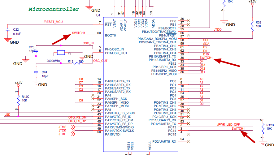
For now I want you to locate the external crystal configuration found just below the green Microcontroller text and to left of the MCU block. This picture should help you find it. It’s wired to PH0/PH1 (pins 5/6) on the microcontroller. This is the 25Mhz crystal oscillator used as the clock source for the STM32F205 MCU. (I suspect that the oscillating frequency shown in the schematic, 25000Mhz, is a typo, since I think that translates to 25Ghz and I’m told this board runs at 25Mhz or 25000Khz.) It’s not critical to understand all the details about how this is wired, however you’ll find it helpful when we go back to the STM32CubeMX tool.
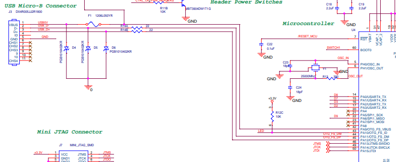
Next, locate the USB Micro-B connector (top left in the picture above) and follow the 5V, D- and D+ lines over to the MCU. They will be mapped to OTC_FS_VBUS, OTC_FS_DM and OTG_FS_DP or PA9, PA11 and PA12 (pins 42/44/45) respectively. While you’re in this same section you should take note of the LED wired to PA10 (pin 43). This is the blue user LED found on the Netduino 2. It has a pull-up resistor wired to +3.3V (this means to turn it on we’ll need to set the pin LOW or 0, which may seem a little odd when programming it ). Ok, now we have enough information to begin our basic pin and clock configurations. We’ll come back to the schematic later when we explore the user BTN and a few other cool wiring pieces the engineers at Secret Labs (now Wilderness Labs) built into this board. Let’s jump back to the STM32CubeMX window.
Clock Configuration
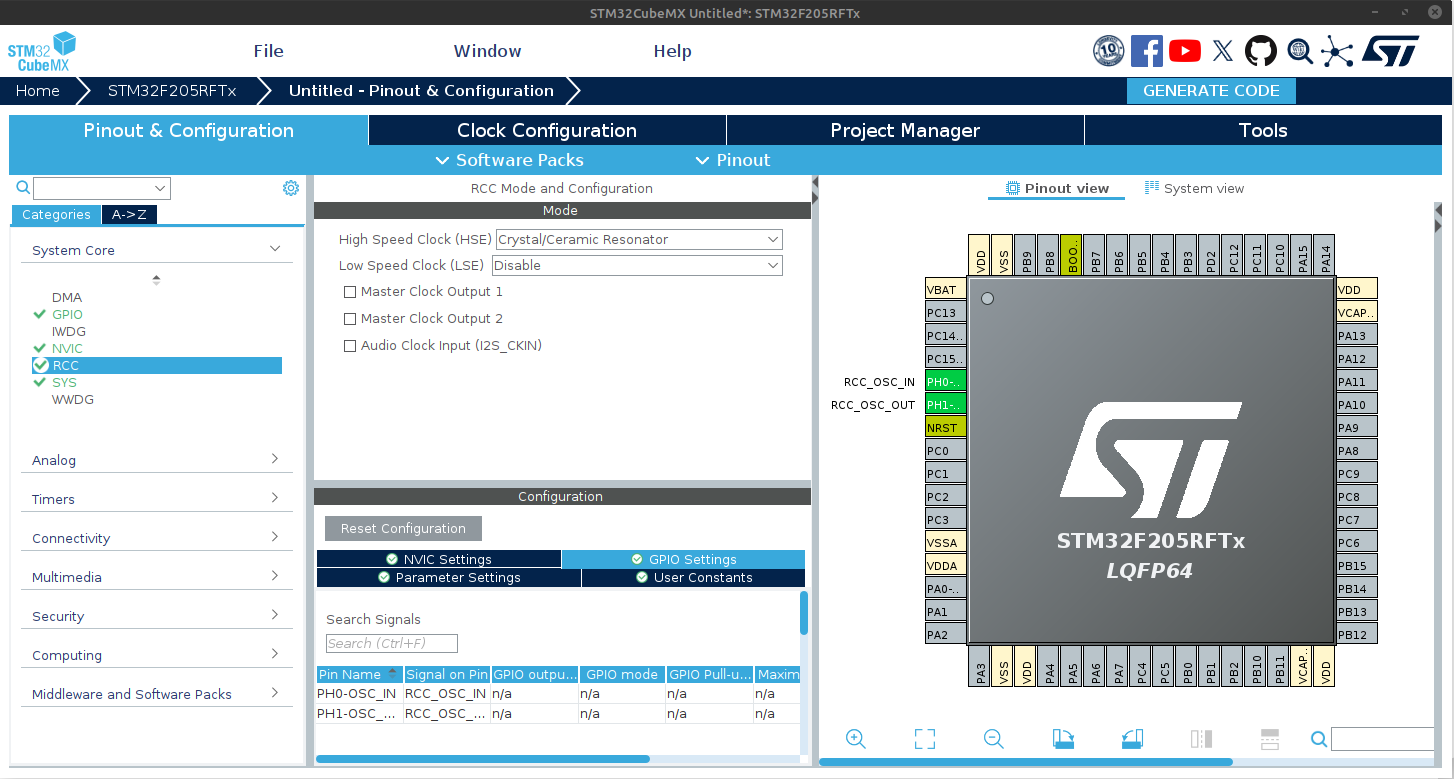
Expand the System Core section under the Categories tab on the left side. Click on RCC (Reset and Clock Control). In the Mode window that comes up, set the High Speed Clock (HSE) to ‘Crystal/Ceramic Resonator’. Notice the pin diagram on the right has changed. The pins PH0/PH1 are now green with RCC_OSC_IN and RCC_OSC_OUT next to them. This matches what we saw on the schematic diagram, pretty cool.
We’ve configured our system to use an external high speed clock crystal, but we haven’t told it anything about the clock or how we want to use it. Let’s do that now by going to the Clock Configuration tab. This tab may seem overwhelming, it did for me when I first looked at it. Don’t worry the tool has some magic built in that will take care of most of this for us. For now we’ll only need to make a few changes on this page and then we’ll tell SMT32CubeMX figure out the rest.
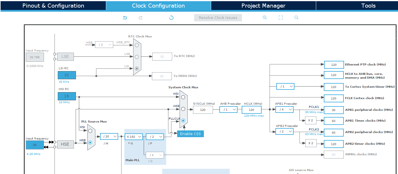
First double check that the HSE Input Frequency box on the left is set to 25 Mhz. Next, follow the HSE line to the right and select the HSE radio button in the PLL Source Mux box. Continue following the arrows to the right and select the PLLCLK radio button in the System Clock Mux box. You may see a few boxes go red. That’s to be expected and we’ll correct that in a minute. Your part of the clock configuration is done. Now we’ll let the tool to do it’s magic. In the top toolbar click the Resolve Clock Issues button. This should modify several of the boxes which should remove those red ones. Here’s how your screen should look now.
USB and LED Pin Setup
We’re almost there. Only a few more things to configure and we can generate our code. Head back to the Pinout & Configuration tab. We’ll start with the USB configuration. Expand the Connectivity section in the tree view on the left and select USB_OTC_FS. In the Mode tool window that comes up, choose Device Only from the Mode dropdown and check the Activate_VBUS checkbox. You should see the PA9/11/12 go green with ‘USB_OTG_FS_xx’ labels next to them.
The USB settings might not be necessary for our simple blink program, but I find it helpful to configure it now so I can easily see what pins are already allocated for a dedicated purpose.
Let’s jump back to the Clock Configuration tab because our USB settings may have caused an error back there. You may have noticed a red x on this tab and when you see the page you’ll probably find a few other boxes are now red. That’s because there is another clock configuration piece needed now for the USB_OTG_FS configured. The simple fix for this is to use the Resolve Clock Issues button one more time. Goodbye red boxes.
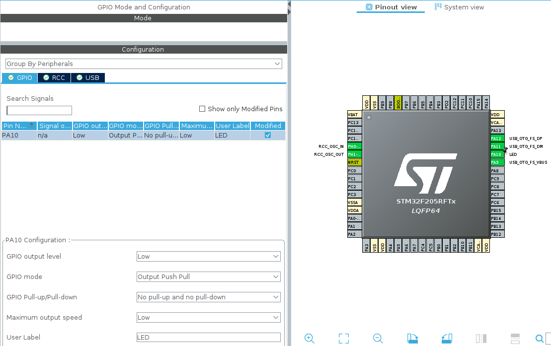
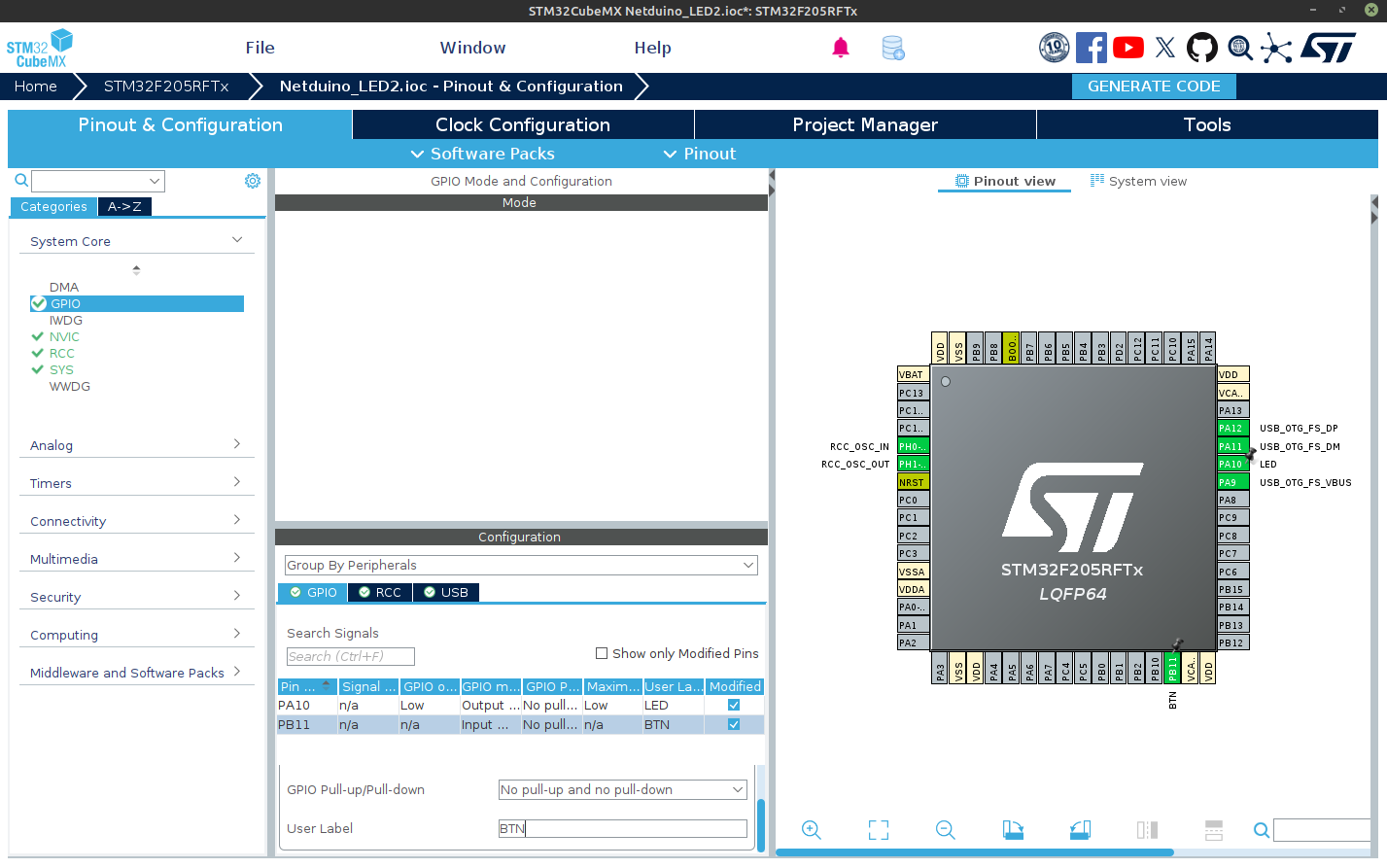
Last configuration step. Back to the Pinout & Configuration tab. Let’s get that LED setup. Using the pin diagram in the right window, locate the PA10 pin on the top right corner between the USB_OTG_FS pins. If you remember our schematic notes, this is where the blue LED is wired to. Place your cursor on that pin and left click. A dropdown menu will appear showing all the peripheral options available on that pin. Select GPIO Output. Back in the left tree view select System Core –> GPIO. Go to the Configuration tool window and click on the PA10 entry and set the User Label to LED. Setting this label isn’t critical, but it’ll make our code a little easier to read since the code can refer to the pin by it’s label. Here’s a final screenshot of the CubeMX pinout view with the LED pin settings.
That’s it. Time to generate some code and get that LED blinking.
Project Manager and Generating Code
Go to the Project Manager tab. Fill in the Project Name, Project Location, and Toolchain/IDE (I used CMAKE & GCC since I’m on Linux and using VS Code). The rest you can leave at their defaults. Now click the Generate Code button above the Tools tab. This may perform a download of the MCU specific code framework. When it’s complete it’ll give you a dialog box. Take note of the location that the code was generated to. We’ll need this in a minute.
You can leave STM32CubeMX open and go back to (or re-open) VS Code. Click the STM32 button in the activity bar to display the STM32 tools window. Then click Import CMake Project and locate the project directory listed on that dialog box when you generated your code. Click Open. Confirm that the Import settings match what you selected, click the Import Project action, then select Open in this window button. If VS Code prompts you for a preset choose Debug.
Adding Code to Blink the LED
Whew, lots of things just happened. Thankfully we don’t have to understand all of it at this point. Remember our goal is to get that LED blinking. To do that we need to add some code to the main() loop. This is the piece of code that will run repeatedly while the MCU is powered. Open /Core/Src/main.c file. Scroll down to the while(1) loop around line 98 and add this code just after the USER CODE BEGIN 3 comment and before the closing }. Your loop should look like this.
  /* USER CODE BEGIN WHILE */
  while (1)
  {
    /* USER CODE END WHILE */

    /* USER CODE BEGIN 3 */
      // Turn LED on (remember setting the pin LOW (0) turns on the LED)
      HAL_GPIO_WritePin(LED_GPIO_Port, LED_Pin, GPIO_PIN_RESET);
      HAL_Delay(500); // pause for .5 sec

      // Turn LED off
      HAL_GPIO_WritePin(LED_GPIO_Port, LED_Pin, GPIO_PIN_SET);
      HAL_Delay(500); // pause for .5 sec

  }
  /* USER CODE END 3 */
If you want a simpler version of that same code you can use the TogglePin method instead of those 6 lines above…
      // OPTION B - Toggle the pin between HIGH (1) and LOW (0)
      HAL_GPIO_TogglePin(LED_GPIO_Port, LED_Pin);
      HAL_Delay(1000); // pause for 1 sec
That’s all the code needed. Right click on the CMakeLists.txt file in the Explorer window and select Build All Projects. When it’s complete you should see something like this in the OUTPUT window.
[build] [23/23] Linking C executable Netduino_LED2.elf
[build] Memory region         Used Size  Region Size  %age Used
[build]              RAM:        3848 B       128 KB      2.94%
[build]            FLASH:        8032 B       768 KB      1.02%
[driver] Build completed: 00:00:02.862
[build] Build finished with exit code 0
The build process generated a binary file that contains the machine level code used by the Netduino. If you take a look at the output window, you’ll see that it named the executable binary file after your project name (Netduino_LED2.elf in the example output above). That is the file we’ll need to download to the Netduino. That file is located in the build/Debug directory of your project. But for now, that file only resides on your PC. This next step will show you how to download that file to the Netduino.
Deploying the Program
- We’ll start this process by opening the STM32 Cube Programmer.
- Place the Netduino 2 into bootloader (or DFU - Device Firmware Update) mode by holding down the user button (BTN) and applying power . You should see both the power LED (white) and the blue user LED light up and stay lit.
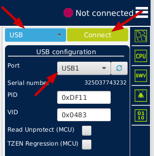
- Back in the STM32 Cube Programmer, select USB from the blue dropdown, USB1 from the Port dropdown (you may need to click the refresh button), and click the green “Connect” button.
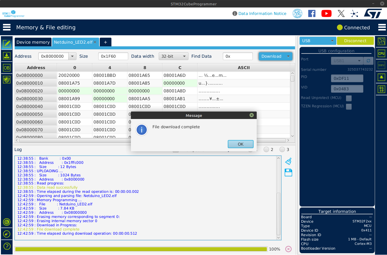
- The screen will change and it will load the binary data that’s already on your Netduino 2 showing you a portion of that on the left hand window. You’ll also see details about the Netduino 2 MCU in the lower right corner under the Target Information section.
- Now click on the Open File tab (or the + tab then Open File) and locate the binary file (.elf) that we generated in the previous section. It should be under the build/Debug directory of your project. The tool will load the file and show you some of the binary details.
- Click the blue Download button to deploy your program to the Netduino 2. Your programmer window should look something like this now.
- The last step is to reset your board by cycling the power.
The Blinking LED
That’s it. If all went well you should see the blue LED blinking away. Well done! You’ve successfully programmed your Netduino 2 using the STM32Cube toolchain. You now have the tools and basic skills necessary to rescue your Netduino2 from the world of .Net. It’s up to you how far you want to take this. Rememeber to…
Stay Curious!
Before We Go
Let’s write some code to use the user button (BTN) along with that LED. This will also help us understand how to modify our project configuration since we need to enable the button using the STM32CubeMX tool. If you go back to the schematic you’ll see the user button (SWITCH1 in the schematic) is wired to two pins, PB11 and PC14. Keep this mind, we’ll need one of those pins in a minute when we configure our board.
Note: The switch is also wired to BOOT0, but that’s used to put the MCU in bootloader mode and probably not programmable.
Back to the STM32 Tools
- Re-open the STM32CubeMX tool. If it’s still open you can just switch to it. If not, click the Launch STM32CubeMx from the STM32 action bar in VS Code.
- If you’re re-opening the STM32CubeMX software you’ll need to re-open the configuration (*.ioc) file using the “Existing Projects” list.
- Once open, left-click on the PB11 pin in the Pinout diagram (pin should be in the bottom right corner), and select GPIO INPUT
- Expand the System Core section in the tree view on the left and select GPIO.
- In the Configuration window click the PB11 entry and change the User Label to “BTN”
Your configuration should now look like this..
- Click the Generate Code button in the top right. This will re-generate your project code and as long as you placed your LED blinking code within a “USER CODE” section, it will retain your previous modifications.
- Back in VS Code, open /Core/Src/main.c file. Scroll down to the **USER CODE BEGIN PV ** section around line 57 and modify the code to look like this.
  /* USER CODE BEGIN PV */
  uint8_t led_state = 0;  // Track the state of the LED
  GPIO_PinState last_button_state = GPIO_PIN_SET; // Track the last position of the BTN
  /* USER CODE END PV */
- Scroll further down to the while(1) loop around line 98, comment out your current LED blinking code and modify it to look something like this.
  while (1) {
    /* USER CODE END WHILE */

    /* USER CODE BEGIN 3 */

    // Labeling the GPIO pin in STM32CubeMX helps make this easier
    // !!! Comment out your existing LED blinking code !!!
    // HAL_GPIO_TogglePin (LED_GPIO_Port, LED_Pin);
    // HAL_Delay(500);

    // Create variable to store the current state of the button
    GPIO_PinState current_button_state = HAL_GPIO_ReadPin(BTN_GPIO_Port, BTN_Pin);

    // Check if the button was pressed and released (transition from SET(HIGH) to RESET(LOW))
    if (last_button_state == GPIO_PIN_SET && current_button_state == GPIO_PIN_RESET) {
      led_state ^= 1; // toggle the LED value
      HAL_GPIO_WritePin(LED_GPIO_Port, LED_Pin,
                        led_state ? GPIO_PIN_RESET : GPIO_PIN_SET);

      // Slight delay to prevent button bounce
      HAL_Delay(50);
    }

    last_button_state = current_button_state;
    HAL_Delay(10);
  }
  /* USER CODE END 3 */
- Right click on the CMakeLists.txt file in the Explorer window and select Build All Projects. Watch the OUTPUT window for the “Build finished with exit code 0” to know that it all compiled correctly.
- Now use the steps in the Deploying the Program section above to push the new binary file to the Netduino2.
- Reset the board by re-applying the power and test it by pressing the button. You should see the blue LED turn on and off at your bidding.
Well Done!
You’ve successfully used both the LED and the BTN on your Netduino 2 without even thinking about .Net or C#. You’ve come a long way.
Other Schematic observations.
Use these notes to try and experiment some more with your Netduino 2.
- Power LED is Switchable (PC13)
- BTN is wired to two GPIO ports (PC14/PB11)
- Power header (3v & 5V) can be turned on and off (PB2)