If you have one of these in your toolbox you might’ve thought they were obsolete. Their .Net Microframework and tools are still around but unfortunately those projects have gone dormant and the toolchain for these boards may not even work on modern operating systems. However, this black clad board with it’s blue pins is not dead. It boasts a powerful 32-bit ARM® microcontroller running at 25Mhz that can run custom firmware and even work with Arduino.
Yep, that’s possible without crossing wires, waving any magic wands, or opening a worm hole to an alternate universe. This post will explain how to setup the Arduino IDE to program your Netduino 2. That means no more .Net MicroFramework, no more Visual Studio 2015. Just you, your Netduino and the Arduino IDE. If you want to skip the fluff and get down to programming, jump to the Arduino setup section below.
Note: The details here are specifically for the Netduino 2, but there is a strong possibility that they will work with other Netduino boards. If you own a different Netduino based on the STM32 chipset, try these steps, altering the board settings as needed, and let me know if you get it working.
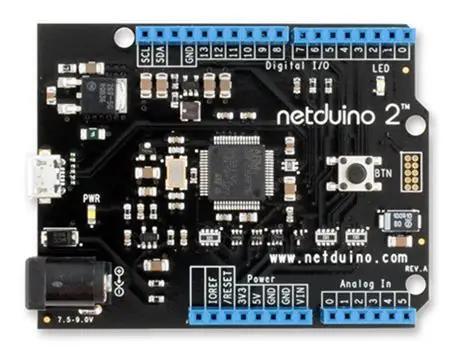
Board Specifics
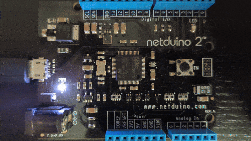
The Netduino 2 board is built with a standard Arduino Uno compatable footprint. It has a 25Mhz clock crystal, USB OTG support, power LED, user-programmable blue LED, user/boot button, 6 Analog pins, and 13-15 digital pins. If you take a look at the Schematic, you’ll find the microcontroller is the STM23F205RFT6, a high-performance ARM® Cortex®-M2 32-bit processor manufactured by STMicroelectronics with a 10 year longevity committment. Which means they’ll support it until at least 2035. Nice to know this board is far from being obsolete. If you’re interested you can read more about this chip in it’s datasheet.
When Wilderness Labs LLC (a.k.a. Secret Labs) designed this board they knew users would want to keep their .Net firmware up to date, so they set it up to with a firmware update (bootloader or DFU - Device Firmware Update) mode. That means you can upload you’re own firmware and use all of the tools in the STMCube ecosystem to program this device (more details on that in future posts). But, whats even more intriguing is that you can use the STM32duino board support package to enable the Arduino IDE to recognize, program and possibly even debug this board. Wow! I have to admit I didn’t think that was possible. Before I tried this, I thought this board would only handle development using .Net MF development.
Arduino Tools from ST
STMicroelectronics manages a Github organization called STM32duino with open source repositories containing the Arduino board support files and tools for their chipsets. Even though it’s not under the official ST support, there’s a community based STM32duino support forum that can connect you STM32duino users who can assist you and help troubleshoot issues.
Setting up the Arduino IDE
- Install the STM32CubeProgrammer
- From the ‘Get Software’ section, install the version appropriate for your OS
- Linux users might have an issue with the PATH not being found when using Arduino to upload your sketch. Here’s what I did to fix it on my machine.
- Ensure you have the Arduino IDE 2 installed. According to the STM32_Core README, that is the only version supported.
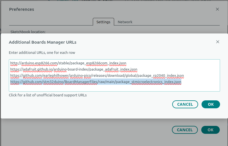
- Add the STM32duino board manager files URL to the IDE settings
- Launch the Arduino IDE and go to File -> Preferences
- Add the following URL to the ‘Additional Boards Manager URLs’ box.
- ‘https://github.com/stm32duino/BoardManagerFiles/raw/main/package_stmicroelectronics_index.json'
- Note: the Icon next to the box will give you a dialog that makes it easier to manage these URLs especially if you use several different URLs.
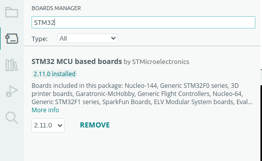
- Add the STM32 Board Package from the Boards Manager
- Go to the Tools –> Board –> Board Manager, or use the icon on the left nav bar
- Search for ‘STM32’ and install the ‘STM32 MCU based boards by STMicroelectronics’ package
- Select and configure the ‘Generic STM32F2 Series’ board
- Back on the Tools -> Board menu you should see a new ‘STM32 MCU based boards’ group.
- Select the ‘Generic STM32F2 Series’ board from the dropdown.
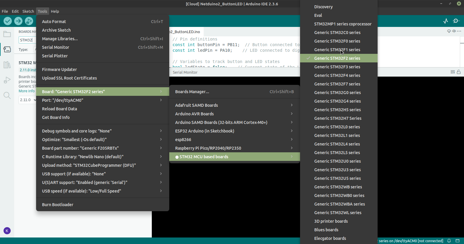
- You’ll notice that your Tools menu now has more options.
- From the Tools menu, set the following additional options
- Board Port Number = ‘STM32F205RFTx’
- Upload Method = ‘STM32CubeProgrammer (DFU)’
- USB Support = ‘CDC generic ‘Serial’ supersede U(S)ART’ (necessary for the Serial Monitor to work)
Blinking the LED
Ok, you’re IDE is all configured let’s get some code written and get that LED blinking. Go ahead and open up the Blink example (File -> Examples -> 01.Basic -> Blink) and modify it to work on the Netduino 2.
First, I don’t think the LED_BUILTIN define has the right pin set so let’s modify the code to use PA10 which, according to the Schematic is where our blue LED is wired too. It’s nice to know that the board definitions have these pins mapped, It will make your life a lot easier going forward.
 // the setup function runs once when you press reset or power the board
 void setup() {
 // initialize digital pin LED_BUILTIN as an output.
 pinMode(PA10, OUTPUT);
 }

 // the loop function runs over and over again forever
 void loop() {
 digitalWrite(PA10, HIGH);  // turn the LED on (HIGH is the voltage level)
 delay(1000);                      // wait for a second
 digitalWrite(PA10, LOW);   // turn the LED off by making the voltage LOW
 delay(1000);                      // wait for a second
 }
Next, we can confirm there are no errors by compiling it. Once that comes back clear, we should be able to upload the code.
But before we go there we need to put our board in Bootloader mode. This is done by holding down the user button (BTN) and applying power. You should see both the power light and the blue LED light up and stay lit.
Now we can hit the upload button in the Ardunio IDE.
NOTE: This is the step that uses the STM32Programmer we installed earlier. If you start getting some ‘PATH’ related errors, be sure to checkout what I did to fix it on my Linux machine.’
ALSO: make sure your using a USB cable that can handle data and not just power. If you get errors indicating that the programmer couldn’t find the board, try a different cable.
If all goes well you should see something like this in the output window.Sketch uses 13016 bytes (9%) of program storage space. Maximum is 131072 bytes. Global variables use 1216 bytes (1%) of dynamic memory, leaving 64320 bytes for local variables. Maximum is 65536 bytes. "" sh "/home/karl/.arduino15/packages/STMicroelectronics/tools/STM32Tools/2.3.1/stm32CubeProg.sh" -i dfu -f "/home/karl/.cache/arduino/sketches/5F095330C80A33F53C3DC2CFF48E18E7/Blink.ino.bin" -o 0x0 -v 0x0483 -p 0xdf11 Selected interface: dfu ------------------------------------------------------------------- STM32CubeProgrammer v2.20.0 ------------------------------------------------------------------- USB speed : Full Speed (12MBit/s) Manuf. ID : STMicroelectronics Product ID : STM32 BOOTLOADER SN : 325D37743232 DFU protocol: 1.1 Board : -- Device ID : 0x0411 Device name : STM32F2xx Flash size : 1 MBytes (default) Device type : MCU Revision ID : -- Device CPU : Cortex-M3 Opening and parsing file: Blink.ino.bin Memory Programming ... File : Blink.ino.bin Size : 13.12 KB Address : 0x08000000 Erasing memory corresponding to segment 0: Erasing internal memory sector 0 Download in Progress: File download complete Time elapsed during download operation: 00:00:00.619 RUNNING Program ... Address: : 0x8000000 Start operation achieved successfully… And your LED should be blinking …
If you’ve made it this far, take a quick moment to celebrate. You’ve just proven that you don’t need .Net or Visual Studio to program your Netduino board.
Well Done!
Blinking on Button Press
Let’s take this a step further and get our beautiful blue LED to blink on command. This step involves us using the built in button (PB11/PC14) to toggle our LED (PA10) instead of using a delay. You can use your current Blink making some adjustments.
Add the following lines to the top of your sketch, (just above the setup() function) to help us track the state of the LED and button.
// Variables to track button and LED states
bool ledState = false;       // Current state of the LED (ON/OFF)
bool lastButtonState = LOW;  // Previous state of the button
bool currentButtonState = LOW;
In the setup() function you’ll initialize the button and set the initial LED state to off. Make sure these are below the pinMode() line that initializes the LED pin.
pinMode(PB11, INPUT_PULLUP); // Set button pin as input with pull-up resistor
digitalWrite(PA10, LOW);     // Ensure LED starts OFF
Moving on to the main loop(). you’re going to replace all of the code in this function with some new logic. First you’ll get the current state of our button. Next, if you’ve fully pressed and released the button (last state was pressed/high and current state is unpressed/low), you can go ahead and toggle the led state by inverting the boolean and then writing to the pin. The delay adds a small pause to debounce the button. Finally you’ll set the lastButtonState so we can keep track of what just happened. Here’s the new loop() function.
void loop() {
    // Read the current state of the button
    currentButtonState = digitalRead(PB11);

    // Check if the button was pressed and released (transition from HIGH to LOW)
    if (lastButtonState == HIGH && currentButtonState == LOW) {
        ledState = !ledState;          // Toggle the LED state
        digitalWrite(PA10, ledState);  // Update the LED
        delay(50);                     // Debounce delay
    }

    // Update the last button state
    lastButtonState = currentButtonState;
}
Run a quick compile to check for any typo’s. Now put the board back in bootloader mode (unplug USB, hold button, plug in USB, release button), and upload the code. The board should automatically reset and begin running the new program. Give it a try by pressing the button and see if the LED switches from off -> on. press it again and it should turn back off. Success!?! I hope so but if not, here’s the full sketch code I successfully ran on my
Netduino 2.// Variables to track button and LED states bool ledState = false; // Current state of the LED (ON/OFF) bool lastButtonState = LOW; // Previous state of the button bool currentButtonState = LOW; // the setup function runs once when you press reset or power the board void setup() { // initialize digital pin LED_BUILTIN as an output. pinMode(PA10, OUTPUT); pinMode(PB11, INPUT_PULLUP); // Set button pin as input with pull-up resistor digitalWrite(PA10, LOW); // Ensure LED starts OFF } // the loop function runs over and over again forever void loop() { // Read the current state of the button currentButtonState = digitalRead(PB11); // Check if the button was pressed and released (transition from HIGH to LOW) if (lastButtonState == HIGH && currentButtonState == LOW) { ledState = !ledState; // Toggle the LED state digitalWrite(PA10, ledState); // Update the LED delay(50); // Debounce delay } // Update the last button state lastButtonState = currentButtonState; }
Extra Credit
Now that you’ve got the basics down, try and figure out how to write some messages back to the serial console. First, make sure you’ve set the USB Support to ‘CDC generic ‘Serial’ supersede U(S)ART’ in the “Tools” menu. You’ll need to add some code to the setup() fuction to enable the serial port and then some Serial.print() or Serial.println() method calls to send out the text. Once you’ve uploaded your code to the Netduino and the device has reset, open the Serial Monitor in the IDE watch for your messages to appear. If you run into difficulities, expand the next section to see the previous example outfitted with some serial output.
Show me the code!
Button Blink with Serial Output
// Variables to track button and LED states
bool ledState = false;    // Current state of the LED (ON/OFF)
bool lastButtonState = LOW; // Previous state of the button
bool currentButtonState = LOW;

// the setup function runs once when you press reset or power the board
void setup() {
    Serial.begin(9600); // Start serial communication at 9600 baud
    Serial.println("Hello, Serial Communication!");

    // initialize digital pin LED_BUILTIN as an output.
    pinMode(PA10, OUTPUT);

    pinMode(PB11, INPUT_PULLUP); // Set button pin as input with pull-up resistor
    digitalWrite(PA10, LOW);       // Ensure LED starts OFF
}

// the loop function runs over and over again forever
void loop() {
    // Read the current state of the button
    currentButtonState = digitalRead(PB11);

    // Check if the button was pressed and released (transition from HIGH to LOW)
    if (lastButtonState == HIGH && currentButtonState == LOW) {
        ledState = !ledState;          // Toggle the LED state
        digitalWrite(PA10, ledState); // Update the LED
        delay(50);                     // Debounce delay
        Serial.print("LED is ");
        Serial.println((ledState == LOW)? "Off" : "On");
    }

    // Update the last button state
    lastButtonState = currentButtonState;
}
Wrap Up
Well you did it! Nice job! You just taught your Netduino a few new tricks. You can officially call it a Netduino. If you ran into any problems you couldn’t solve or noticed something amiss in the steps above let me know and I’ll do my best to fix it. Otherwise I’ll wish you great success with your revived Netduino. May you always…
Stay Curious!
Appendix A - STM32F205 Pin to Arduino Pin Mapping
To help you with programming your Netduino with Arduino you’ll need to know how the pins are mapped between the MCU and the boards pins. Here’s what I was able to extract from the Netduino schematic.
| MCU Pin | Board Pin |
|---|---|
| PC0 | A0 |
| PC1 | A1 |
| PC2 | A2 |
| PC3 | A3 |
| PC4 | A4 |
| PC5 | A5 |
| ———- | ———- |
| PC7 | D0 |
| PC6 | D1 |
| PA3 | D2 |
| PA2 | D3 |
| PB12 | D4 |
| PB8 | D5 |
| PB9 | D6 |
| PA1 | D7 |
| PA0 | D8 |
| PA6 | D9 |
| PB10 | D10 |
| PB15 | D11 |
| PB14 | D12 |
| ———- | ———- |
| PB7 | SCA |
| PB6 | SCL |
| ———- | ———- |
| PA10 | Blue LED |
| PC13 | Power LED |
| PB11 | User Button |
| PC14 | User Button |
| ———- | ———- |
| PA14 | JTAG CLK |
| PA15 | JTAG DI |
| PA13 | JTAG DIO |
| PB3 | JTAG DO |
| ———- | ———- |
| PA10 | USB OTG DB |
| PA11 | USB OTG DP |
Appendix B - Further Exploring the MCU
As I read the datasheet and look again at the Netduino schematic, I see that this MCU can do quite a bit more than I was aware. There are several features that may be worth the time to explore. Among them are, the CAN bus, SPI, UART/USART, PWM. At first glance it would seem that the Netduino board would support all of these. The CAN may require an external transciever, but the pins may be available. I think CAN1 is on PB8/9 pins which map to D5/D6 on the Netduino.
Another area worth exploring would be the JTAG connector and the possibility of using an ST-Link hardware to run the Arduino debugger. This ST Community Post indicates that it is possible for some ST Boards to be debugged using Arduino. The only difference is that the ST boards come with a built in ST-Link programmer/debugger. It might be possible to use the JTAG connector on the Netduino to attach the ST-Link device and use it within Arduino.